Draw Decision Boundary for 8 Psk 7 Around 1 Box
Phase-shift keying (PSK) is a digital modulation process which conveys data by irresolute (modulating) the phase of a constant frequency reference signal (the carrier wave). The modulation is accomplished by varying the sine and cosine inputs at a precise fourth dimension. It is widely used for wireless LANs, RFID and Bluetooth communication.
Whatever digital modulation scheme uses a finite number of distinct signals to stand for digital data. PSK uses a finite number of phases, each assigned a unique pattern of binary digits. Usually, each phase encodes an equal number of $.25. Each design of bits forms the symbol that is represented by the item phase. The demodulator, which is designed specifically for the symbol-set used past the modulator, determines the phase of the received signal and maps it dorsum to the symbol it represents, thus recovering the original information. This requires the receiver to be able to compare the phase of the received bespeak to a reference signal – such a arrangement is termed coherent (and referred to every bit CPSK).
CPSK requires a complicated demodulator, because it must excerpt the reference wave from the received point and keep runway of information technology, to compare each sample to. Alternatively, the phase shift of each symbol sent can exist measured with respect to the phase of the previous symbol sent. Because the symbols are encoded in the difference in phase between successive samples, this is called differential phase-shift keying (DPSK). DPSK tin be significantly simpler to implement than ordinary PSK, as it is a 'not-coherent' scheme, i.e. there is no need for the demodulator to keep track of a reference wave. A trade-off is that information technology has more than demodulation errors.
Introduction [edit]
There are three major classes of digital modulation techniques used for transmission of digitally represented data:
- Aamplitude-shift keying (ASK)
- Frequency-shift keying (FSK)
- Stage-shift keying (PSK)
All convey data by changing some attribute of a base point, the carrier wave (usually a sinusoid), in response to a information signal. In the case of PSK, the phase is changed to stand for the data signal. There are ii key ways of utilizing the phase of a signal in this way:
- By viewing the stage itself as conveying the information, in which case the demodulator must have a reference signal to compare the received signal's phase against; or
- By viewing the change in the phase equally conveying information – differential schemes, some of which practise not need a reference carrier (to a certain extent).
A convenient method to represent PSK schemes is on a constellation diagram. This shows the points in the complex plane where, in this context, the real and imaginary axes are termed the in-phase and quadrature axes respectively due to their ninety° separation. Such a representation on perpendicular axes lends itself to straightforward implementation. The amplitude of each point along the in-phase centrality is used to modulate a cosine (or sine) moving ridge and the amplitude along the quadrature axis to modulate a sine (or cosine) wave. By convention, in-stage modulates cosine and quadrature modulates sine.
In PSK, the constellation points called are unremarkably positioned with uniform angular spacing effectually a circle. This gives maximum stage-separation between adjacent points and thus the best immunity to corruption. They are positioned on a circle so that they can all be transmitted with the same energy. In this mode, the moduli of the complex numbers they represent volition be the same and thus and then volition the amplitudes needed for the cosine and sine waves. Two common examples are "binary phase-shift keying" (BPSK) which uses two phases, and "quadrature phase-shift keying" (QPSK) which uses iv phases, although any number of phases may be used. Since the data to exist conveyed are usually binary, the PSK scheme is usually designed with the number of constellation points existence a power of two.
Definitions [edit]
For determining mistake-rates mathematically, some definitions will exist needed:
volition give the probability that a unmarried sample taken from a random procedure with nix-mean and unit of measurement-variance Gaussian probability density role volition be greater or equal to . It is a scaled form of the complementary Gaussian error role:


- .

The error rates quoted hither are those in additive white Gaussian noise (AWGN). These error rates are lower than those computed in fading channels, hence, are a good theoretical benchmark to compare with.
Applications [edit]
Owing to PSK's simplicity, particularly when compared with its competitor quadrature amplitude modulation, information technology is widely used in existing technologies.
The wireless LAN standard, IEEE 802.11b-1999,[1] [two] uses a variety of different PSKs depending on the information charge per unit required. At the basic charge per unit of 1Mbit/s, it uses DBPSK (differential BPSK). To provide the extended charge per unit of twoMbit/s, DQPSK is used. In reaching 5.vMbit/s and the total charge per unit of 11Mbit/south, QPSK is employed, simply has to exist coupled with complementary code keying. The higher-speed wireless LAN standard, IEEE 802.11g-2003,[one] [iii] has eight data rates: 6, 9, 12, eighteen, 24, 36, 48 and 54Mbit/south. The 6 and ixMbit/due south modes use OFDM modulation where each sub-carrier is BPSK modulated. The 12 and 18Mbit/due south modes use OFDM with QPSK. The fastest four modes utilise OFDM with forms of quadrature aamplitude modulation.
Because of its simplicity, BPSK is appropriate for low-cost passive transmitters, and is used in RFID standards such as ISO/IEC 14443 which has been adopted for biometric passports, credit cards such every bit American Express's ExpressPay, and many other applications.[iv]
Bluetooth 2 uses -DQPSK at its lower rate (2Mbit/s) and 8-DPSK at its higher charge per unit (3Mbit/s) when the link between the two devices is sufficiently robust. Bluetooth 1 modulates with Gaussian minimum-shift keying, a binary scheme, so either modulation pick in version 2 will yield a higher data-charge per unit. A similar technology, IEEE 802.15.four (the wireless standard used past ZigBee) also relies on PSK using ii frequency bands: 868–915MHz with BPSK and at two.4GHz with OQPSK.

Both QPSK and 8PSK are widely used in satellite broadcasting. QPSK is notwithstanding widely used in the streaming of SD satellite channels and some Hard disk drive channels. High definition programming is delivered almost exclusively in 8PSK due to the college bitrates of HD video and the loftier cost of satellite bandwidth.[v] The DVB-S2 standard requires support for both QPSK and 8PSK. The chipsets used in new satellite set top boxes, such as Broadcom's 7000 series support 8PSK and are astern compatible with the older standard.[6]
Historically, vocalisation-band synchronous modems such equally the Bell 201, 208, and 209 and the CCITT V.26, V.27, Five.29, V.32, and V.34 used PSK.[7]
Binary phase-shift keying (BPSK) [edit]

BPSK (also sometimes called PRK, phase reversal keying, or 2PSK) is the simplest form of stage shift keying (PSK). It uses ii phases which are separated by 180° and and then can besides be termed 2-PSK. It does not particularly thing exactly where the constellation points are positioned, and in this figure they are shown on the existent centrality, at 0° and 180°. Therefore, it handles the highest noise level or distortion before the demodulator reaches an incorrect conclusion. That makes it the most robust of all the PSKs. It is, however, only able to attune at anebit/symbol (as seen in the figure) and and then is unsuitable for high data-charge per unit applications.
In the presence of an arbitrary phase-shift introduced past the communications aqueduct, the demodulator (see, e.g. Costas loop) is unable to tell which constellation signal is which. Every bit a consequence, the data is oft differentially encoded prior to modulation.
BPSK is functionally equivalent to 2-QAM modulation.
Implementation [edit]
The general form for BPSK follows the equation:

This yields two phases, 0 and π. In the specific form, binary data is often conveyed with the post-obit signals:[ citation needed ]
- for binary "0"
- for binary "i"


where f is the frequency of the base band.
Hence, the signal space tin can be represented by the single basis function

where 1 is represented by and 0 is represented past . This assignment is arbitrary.


This use of this ground office is shown at the end of the next section in a signal timing diagram. The topmost signal is a BPSK-modulated cosine moving ridge that the BPSK modulator would produce. The chip-stream that causes this output is shown above the indicate (the other parts of this figure are relevant just to QPSK). Later modulation, the base band signal will be moved to the high frequency ring by multiplying .

Bit fault rate [edit]
The chip error rate (BER) of BPSK under additive white Gaussian noise (AWGN) can be calculated as:[8]
- or


Since there is only ane bit per symbol, this is also the symbol fault rate.
Quadrature phase-shift keying (QPSK) [edit]

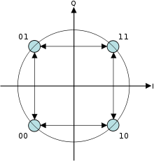
Constellation diagram for QPSK with Grey coding. Each adjacent symbol only differs past one flake.
Sometimes this is known as quadriphase PSK, 4-PSK, or 4-QAM. (Although the root concepts of QPSK and 4-QAM are different, the resulting modulated radio waves are exactly the aforementioned.) QPSK uses four points on the constellation diagram, equispaced around a circle. With iv phases, QPSK can encode two $.25 per symbol, shown in the diagram with Gray coding to minimize the bit fault rate (BER) – sometimes misperceived as twice the BER of BPSK.
The mathematical analysis shows that QPSK tin can be used either to double the information charge per unit compared with a BPSK system while maintaining the aforementioned bandwidth of the bespeak, or to maintain the data-rate of BPSK just halving the bandwidth needed. In this latter case, the BER of QPSK is exactly the same as the BER of BPSK – and believing differently is a common confusion when considering or describing QPSK. The transmitted carrier can undergo numbers of stage changes.
Given that radio communication channels are allocated by agencies such as the Federal Communications Committee giving a prescribed (maximum) bandwidth, the advantage of QPSK over BPSK becomes evident: QPSK transmits twice the information rate in a given bandwidth compared to BPSK - at the aforementioned BER. The engineering penalty that is paid is that QPSK transmitters and receivers are more complicated than the ones for BPSK. Nonetheless, with modern electronics engineering science, the penalty in cost is very moderate.
As with BPSK, there are phase ambivalence problems at the receiving terminate, and differentially encoded QPSK is often used in practice.
Implementation [edit]
The implementation of QPSK is more than full general than that of BPSK and also indicates the implementation of higher-order PSK. Writing the symbols in the constellation diagram in terms of the sine and cosine waves used to transmit them:

This yields the four phases π/4, 3π/4, 5π/iv and 7π/4 as needed.
This results in a two-dimensional bespeak infinite with unit basis functions

The first basis role is used equally the in-phase component of the signal and the second as the quadrature component of the signal.
Hence, the signal constellation consists of the point-space 4 points

The factors of 1/2 bespeak that the total power is split equally between the two carriers.
Comparing these footing functions with that for BPSK shows clearly how QPSK tin be viewed equally ii contained BPSK signals. Note that the signal-infinite points for BPSK practice not need to split the symbol (bit) energy over the two carriers in the scheme shown in the BPSK constellation diagram.
QPSK systems can be implemented in a number of ways. An illustration of the major components of the transmitter and receiver structure are shown below.
![]()
Conceptual transmitter structure for QPSK. The binary data stream is split into the in-phase and quadrature-phase components. These are then separately modulated onto 2 orthogonal footing functions. In this implementation, two sinusoids are used. Later on, the two signals are superimposed, and the resulting signal is the QPSK indicate. Note the use of polar non-render-to-zilch encoding. These encoders tin can be placed before for binary data source, but accept been placed afterwards to illustrate the conceptual difference betwixt digital and analog signals involved with digital modulation.
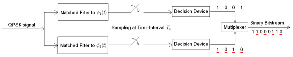
Receiver construction for QPSK. The matched filters tin can be replaced with correlators. Each detection device uses a reference threshold value to determine whether a 1 or 0 is detected.
Probability of mistake [edit]
Although QPSK tin be viewed as a 4th modulation, it is easier to see it as two independently modulated quadrature carriers. With this interpretation, the even (or odd) bits are used to modulate the in-phase component of the carrier, while the odd (or even) bits are used to modulate the quadrature-phase component of the carrier. BPSK is used on both carriers and they can be independently demodulated.
Every bit a event, the probability of bit-error for QPSK is the aforementioned as for BPSK:
Nevertheless, in gild to achieve the same chip-error probability as BPSK, QPSK uses twice the ability (since two bits are transmitted simultaneously).
The symbol fault rate is given past:
![{\displaystyle {\begin{aligned}P_{s}&=1-\left(1-P_{b}\right)^{2}\\&=2Q\left({\sqrt {\frac {E_{s}}{N_{0}}}}\right)-\left[Q\left({\sqrt {\frac {E_{s}}{N_{0}}}}\right)\right]^{2}.\end{aligned}}}](https://wikimedia.org/api/rest_v1/media/math/render/svg/f83586ff4bc11f3ac6369902becbeba4313b675a)
If the signal-to-dissonance ratio is high (as is necessary for practical QPSK systems) the probability of symbol error may be approximated:

The modulated signal is shown below for a brusk segment of a random binary information-stream. The ii carrier waves are a cosine wave and a sine wave, as indicated past the signal-space assay above. Here, the odd-numbered bits have been assigned to the in-phase component and the even-numbered bits to the quadrature component (taking the start fleck as number 1). The total signal – the sum of the two components – is shown at the lesser. Jumps in phase tin be seen equally the PSK changes the phase on each component at the start of each bit-period. The topmost waveform alone matches the description given for BPSK above.
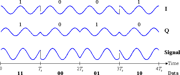
Timing diagram for QPSK. The binary information stream is shown beneath the fourth dimension axis. The two signal components with their chip assignments are shown at the tiptop, and the total combined indicate at the lesser. Note the precipitous changes in phase at some of the bit-period boundaries.
The binary data that is conveyed by this waveform is: 11000110.
- The odd bits, highlighted here, contribute to the in-phase component: aneane0001one0
- The fifty-fifty bits, highlighted hither, contribute to the quadrature-phase component: 1i0001ane0
Variants [edit]
Offset QPSK (OQPSK) [edit]
Signal doesn't pass through the origin, because merely one bit of the symbol is inverse at a time.
Commencement quadrature phase-shift keying (OQPSK) is a variant of phase-shift keying modulation using four different values of the phase to transmit. It is sometimes called staggered quadrature phase-shift keying (SQPSK).

Difference of the phase between QPSK and OQPSK
Taking four values of the stage (two bits) at a fourth dimension to construct a QPSK symbol can permit the phase of the signal to jump by as much as 180° at a time. When the bespeak is low-pass filtered (as is typical in a transmitter), these phase-shifts outcome in large aamplitude fluctuations, an undesirable quality in communication systems. By offsetting the timing of the odd and even bits by one flake-flow, or one-half a symbol-period, the in-stage and quadrature components will never change at the same fourth dimension. In the constellation diagram shown on the right, it can be seen that this will limit the phase-shift to no more than than xc° at a time. This yields much lower aamplitude fluctuations than non-offset QPSK and is sometimes preferred in practice.
The picture on the right shows the departure in the behavior of the phase betwixt ordinary QPSK and OQPSK. It can be seen that in the showtime plot the phase tin modify by 180° at once, while in OQPSK the changes are never greater than 90°.
The modulated signal is shown below for a short segment of a random binary data-stream. Annotation the one-half symbol-menstruum commencement between the two component waves. The sudden phase-shifts occur most twice equally oft as for QPSK (since the signals no longer change together), but they are less severe. In other words, the magnitude of jumps is smaller in OQPSK when compared to QPSK.

Timing diagram for outset-QPSK. The binary data stream is shown below the time axis. The ii signal components with their bit assignments are shown the peak and the total, combined signal at the bottom. Note the half-period start between the two betoken components.
SOQPSK [edit]
The license-gratis shaped-offset QPSK (SOQPSK) is interoperable with Feher-patented QPSK (FQPSK), in the sense that an integrate-and-dump offset QPSK detector produces the same output no matter which kind of transmitter is used.[9]
These modulations carefully shape the I and Q waveforms such that they change very smoothly, and the bespeak stays constant-aamplitude fifty-fifty during betoken transitions. (Rather than traveling instantly from one symbol to another, or even linearly, it travels smoothly around the constant-amplitude circle from one symbol to the next.) SOQPSK modulation can be represented as the hybrid of QPSK and MSK: SOQPSK has the same signal constellation every bit QPSK, even so the phase of SOQPSK is always stationary.[10] [11]
The standard description of SOQPSK-TG involves ternary symbols.[12] SOQPSK is one of the well-nigh spread modulation schemes in application to LEO satellite communications.[xiii]
π/4-QPSK [edit]

Dual constellation diagram for π/4-QPSK. This shows the two divide constellations with identical Greyness coding only rotated by 45° with respect to each other.
This variant of QPSK uses two identical constellations which are rotated past 45° ( radians, hence the proper name) with respect to one some other. Usually, either the even or odd symbols are used to select points from one of the constellations and the other symbols select points from the other constellation. This too reduces the phase-shifts from a maximum of 180°, but only to a maximum of 135° and so the amplitude fluctuations of -QPSK are between OQPSK and not-offset QPSK.
One belongings this modulation scheme possesses is that if the modulated point is represented in the complex domain, transitions between symbols never laissez passer through 0. In other words, the point does not pass through the origin. This lowers the dynamical range of fluctuations in the signal which is desirable when engineering communications signals.
On the other hand, -QPSK lends itself to easy demodulation and has been adopted for use in, for instance, TDMA cellular telephone systems.
The modulated point is shown beneath for a short segment of a random binary data-stream. The construction is the same as to a higher place for ordinary QPSK. Successive symbols are taken from the ii constellations shown in the diagram. Thus, the outset symbol (one one) is taken from the "blueish" constellation and the second symbol (0 0) is taken from the "green" constellation. Notation that magnitudes of the two component waves change every bit they switch between constellations, just the total indicate's magnitude remains constant (constant envelope). The stage-shifts are betwixt those of the two previous timing-diagrams.

Timing diagram for π/4-QPSK. The binary data stream is shown beneath the time centrality. The two signal components with their chip assignments are shown the acme and the total, combined bespeak at the bottom. Note that successive symbols are taken alternately from the two constellations, starting with the "blue" one.
DPQPSK [edit]
Dual-polarization quadrature phase shift keying (DPQPSK) or dual-polarization QPSK - involves the polarization multiplexing of two different QPSK signals, thus improving the spectral efficiency past a gene of 2. This is a price-effective alternative to utilizing 16-PSK, instead of QPSK to double the spectral efficiency.j
Higher-club PSK [edit]
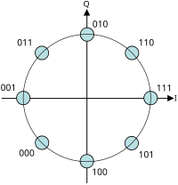
Constellation diagram for 8-PSK with Gray coding
Whatever number of phases may be used to construct a PSK constellation simply eight-PSK is unremarkably the highest order PSK constellation deployed. With more than than 8 phases, the error-rate becomes besides high and at that place are ameliorate, though more complex, modulations available such every bit quadrature amplitude modulation (QAM). Although whatsoever number of phases may exist used, the fact that the constellation must commonly deal with binary data means that the number of symbols is usually a power of ii to allow an integer number of bits per symbol.
Bit error rate [edit]
For the full general Thousand-PSK there is no unproblematic expression for the symbol-error probability if . Unfortunately, it can only be obtained from


where

and and are each Gaussian random variables.


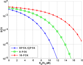
Flake-error rate curves for BPSK, QPSK, 8-PSK and xvi-PSK, additive white Gaussian racket channel
This may be approximated for loftier and high by:


The bit-error probability for -PSK tin can merely be determined exactly in one case the bit-mapping is known. Nevertheless, when Grey coding is used, the most probable error from one symbol to the next produces only a single flake-error and

(Using Grey coding allows us to approximate the Lee altitude of the errors as the Hamming distance of the errors in the decoded bitstream, which is easier to implement in hardware.)
The graph on the left compares the chip-mistake rates of BPSK, QPSK (which are the same, every bit noted above), 8-PSK and 16-PSK. Information technology is seen that college-society modulations showroom higher error-rates; in exchange notwithstanding they deliver a college raw data-rate.
Bounds on the mistake rates of various digital modulation schemes tin can be computed with application of the union bound to the signal constellation.
Spectral efficiency [edit]
Bandwidth (or spectral) efficiency of M-PSK modulation schemes increases with increasing of modulation order M (unlike, for example, K-FSK):[14]
![{\displaystyle \rho ={\frac {\log _{2}M}{2}}\quad [({\text{bits}}/{\text{s}})/{\text{Hz}}]}](https://wikimedia.org/api/rest_v1/media/math/render/svg/5a61e49e0f629d1a571189de0c9b559a9273d777)
The same human relationship holds true for Yard-QAM.[15]
Differential phase-shift keying (DPSK) [edit]
Differential encoding [edit]
Differential phase shift keying (DPSK) is a common form of phase modulation that conveys data past changing the stage of the carrier wave. As mentioned for BPSK and QPSK in that location is an ambiguity of stage if the constellation is rotated by some result in the communications aqueduct through which the betoken passes. This trouble can exist overcome by using the data to change rather than set the phase.
For example, in differentially encoded BPSK a binary "1" may be transmitted past adding 180° to the current phase and a binary "0" by adding 0° to the current stage. Some other variant of DPSK is Symmetric Differential Phase Shift keying, SDPSK, where encoding would be +90° for a "1" and −ninety° for a "0".
In differentially encoded QPSK (DQPSK), the phase-shifts are 0°, 90°, 180°, −90° corresponding to data "00", "01", "11", "ten". This kind of encoding may be demodulated in the same way as for not-differential PSK but the phase ambiguities can be ignored. Thus, each received symbol is demodulated to i of the points in the constellation and a comparator then computes the difference in phase between this received signal and the preceding one. The difference encodes the information as described to a higher place. Symmetric differential quadrature phase shift keying (SDQPSK) is similar DQPSK, just encoding is symmetric, using phase shift values of −135°, −45°, +45° and +135°.
The modulated bespeak is shown below for both DBPSK and DQPSK equally described to a higher place. In the effigy, it is causeless that the signal starts with goose egg phase, and so there is a phase shift in both signals at .


Timing diagram for DBPSK and DQPSK. The binary data stream is above the DBPSK signal. The individual bits of the DBPSK betoken are grouped into pairs for the DQPSK signal, which only changes every Tsouthward = 2Tb .
Analysis shows that differential encoding approximately doubles the error rate compared to ordinary -PSK simply this may be overcome by only a small increase in . Furthermore, this analysis (and the graphical results below) are based on a organisation in which the only corruption is additive white Gaussian noise (AWGN). Notwithstanding, there will also be a physical channel betwixt the transmitter and receiver in the advice system. This channel will, in general, introduce an unknown phase-shift to the PSK signal; in these cases the differential schemes tin yield a better error-rate than the ordinary schemes which rely on precise phase information.
One of the most popular applications of DPSK is the Bluetooth standard where -DQPSK and viii-DPSK were implemented.
Demodulation [edit]

BER comparison between DBPSK, DQPSK and their non-differential forms using Gray coding and operating in white dissonance
For a indicate that has been differentially encoded, there is an obvious culling method of demodulation. Instead of demodulating as usual and ignoring carrier-phase ambivalence, the phase between two successive received symbols is compared and used to decide what the information must have been. When differential encoding is used in this manner, the scheme is known every bit differential phase-shift keying (DPSK). Annotation that this is subtly different from just differentially encoded PSK since, upon reception, the received symbols are not decoded one-by-one to constellation points just are instead compared direct to one another.
Call the received symbol in the th timeslot and let information technology have phase . Presume without loss of generality that the phase of the carrier moving ridge is zero. Denote the additive white Gaussian racket (AWGN) term as . Then


The decision variable for the thursday symbol and the th symbol is the phase difference between and . That is, if is projected onto , the conclusion is taken on the stage of the resultant complex number:


where superscript * denotes circuitous conjugation. In the absence of dissonance, the phase of this is , the stage-shift between the ii received signals which can be used to determine the data transmitted.

The probability of mistake for DPSK is difficult to summate in general, but, in the case of DBPSK it is:
- [16]

which, when numerically evaluated, is only slightly worse than ordinary BPSK, particularly at higher values.
Using DPSK avoids the need for possibly complex carrier-recovery schemes to provide an accurate stage estimate and can be an attractive alternative to ordinary PSK.
In optical communications, the information can exist modulated onto the phase of a laser in a differential way. The modulation is a laser which emits a continuous wave, and a Mach–Zehnder modulator which receives electrical binary data. For the case of BPSK, the light amplification by stimulated emission of radiation transmits the field unchanged for binary 'ane', and with reverse polarity for '0'. The demodulator consists of a delay line interferometer which delays one bit, so ii bits tin can be compared at one time. In further processing, a photodiode is used to transform the optical field into an electrical current, so the information is inverse dorsum into its original state.
The scrap-error rates of DBPSK and DQPSK are compared to their non-differential counterparts in the graph to the right. The loss for using DBPSK is minor enough compared to the complexity reduction that it is often used in communications systems that would otherwise utilise BPSK. For DQPSK though, the loss in functioning compared to ordinary QPSK is larger and the system designer must balance this against the reduction in complexity.
Instance: Differentially encoded BPSK [edit]
![]()
Differential encoding/decoding organisation diagram
At the time-slot telephone call the bit to exist modulated , the differentially encoded bit and the resulting modulated point . Assume that the constellation diagram positions the symbols at ±1 (which is BPSK). The differential encoder produces:


where indicates binary or modulo-two improver.


BER comparing between BPSK and differentially encoded BPSK operating in white noise
And so only changes state (from binary "0" to binary "i" or from binary "1" to binary "0") if is a binary "1". Otherwise it remains in its previous state. This is the description of differentially encoded BPSK given in a higher place.
The received betoken is demodulated to yield and then the differential decoder reverses the encoding procedure and produces


since binary subtraction is the aforementioned as binary addition.
Therefore, if and differ and if they are the same. Hence, if both and are inverted, will still be decoded correctly. Thus, the 180° stage ambivalence does not thing.


Differential schemes for other PSK modulations may be devised along like lines. The waveforms for DPSK are the same as for differentially encoded PSK given above since the merely modify betwixt the two schemes is at the receiver.
The BER curve for this instance is compared to ordinary BPSK on the right. As mentioned higher up, whilst the error charge per unit is approximately doubled, the increment needed in to overcome this is small. The increase in required to overcome differential modulation in coded systems, however, is larger – typically about 3 dB. The performance degradation is a issue of noncoherent transmission – in this instance information technology refers to the fact that tracking of the phase is completely ignored.
Mutual information with condiment white Gaussian noise [edit]

Mutual information of PSK over the AWGN channel
The mutual information of PSK can be evaluated in additive Gaussian noise by numerical integration of its definition.[17] The curves of mutual data saturate to the number of bits carried by each symbol in the limit of infinite signal to noise ratio . On the contrary, in the limit of small signal to noise ratios the mutual information approaches the AWGN channel capacity, which is the supremum among all possible choices of symbol statistical distributions.

At intermediate values of betoken to noise ratios the common data (MI) is well approximated by:[17]

The mutual information of PSK over the AWGN aqueduct is generally farther to the AWGN aqueduct chapters than QAM modulation formats.
See as well [edit]
- Binary start carrier modulation
- Differential coding
- Modulation – for an overview of all modulation schemes
- Stage modulation (PM) – the analogue equivalent of PSK
- Polar modulation
- PSK31
- PSK63
Notes [edit]
- ^ a b IEEE Std 802.11-1999: Wireless LAN Medium Access Command (MAC) and Physical Layer (PHY) Specifications – the overarching IEEE 802.11 specification. Archived Baronial 28, 2007, at the Wayback Machine
- ^ IEEE Std 802.11b-1999 (R2003) – the IEEE 802.11b specification.
- ^ IEEE Std 802.11g-2003 – the IEEE 802.11g specification.
- ^ Understanding the Requirements of ISO/IEC 14443 for Type B Proximity Contactless Identification Cards, Awarding Note, Rev. 2056B–RFID–eleven/05, 2005, ATMEL.
- ^ "How Communications Satellites Work". Planet Trick. 2014.
- ^ "Archived re-create". Archived from the original on 2015-09-xv. Retrieved 2015-09-08 .
{{cite spider web}}: CS1 maint: archived copy as title (link) - ^ "Local and Remote Modems" (PDF). Black Box. Blackness Box Network Services. Archived from the original (PDF) on December 22, 2015. Retrieved Dec 20, 2015.
- ^ Communications Systems, H. Stern & S. Mahmoud, Pearson Prentice Hall, 2004, p. 283.
- ^ Tom Nelson, Erik Perrins, and Michael Rice. "Common detectors for Tier 1 modulations" Archived 2012-09-17 at the Wayback Machine. T. Nelson, E. Perrins, Yard. Rice. "Common detectors for shaped beginning QPSK (SOQPSK) and Feher-patented QPSK (FQPSK)" Nelson, T.; Perrins, Due east.; Rice, M. (2005). "Common detectors for shaped starting time QPSK (SOQPSK) and Feher-patented QPSK (FQPSK)". GLOBECOM '05. IEEE Global Telecommunications Conference, 2005. pp. 5 pp. doi:10.1109/GLOCOM.2005.1578470. ISBN0-7803-9414-three. S2CID 11020777. ISBN 0-7803-9414-3
- ^ Hill, Terrance J. "A non-proprietary, abiding envelope, variant of shaped offset QPSK (SOQPSK) for improved spectral containment and detection efficiency." MILCOM 2000. 21st Century Armed forces Communications Conference Proceedings. Vol. 1. IEEE, 2000.
- ^ Li, Lifang, and M. K. Simon. "Performance of coded offset quadrature stage-shift keying (OQPSK) and MIL-STD shaped OQPSK (SOQPSK) with iterative decoding." Interplanetary Network Prog. Rep. 42 (2004).
- ^ Sahin, C. and Perrins, E., 2011, Nov. The chapters of SOQPSK-TG. In 2011-MILCOM 2011 Military Communications Conference (pp. 555-560). IEEE.
- ^ Saeed, N., Elzanaty, A., Almorad, H., Dahrouj, H., Al-Naffouri, T.Y. and Alouini, Thousand.Due south., 2020. Cubesat communications: Recent advances and future challenges. IEEE Communications Surveys & Tutorials.
- ^ Haykin, South., 2001. Communication Systems, John Wiley&Sons. Inc. - p. 368
- ^ Link Budget Assay: Digital Modulation, Part 3 (world wide web.AtlantaRF.com)
- ^ G.L. Stüber, "Soft Decision Straight-Sequence DPSK Receivers," IEEE Transactions on Vehicular Technology, vol. 37, no. three, pp. 151–157, August 1988.
- ^ a b Blahut, R. E. (1988). Principles and Practice of Information Theory. Boston, MA, USA: Addison Wesley Publishing Visitor. ISBN0-201-10709-0.
References [edit]
The annotation and theoretical results in this article are based on material presented in the following sources:
- Proakis, John G. (1995). Digital Communications. Singapore: McGraw Hill. ISBN0-07-113814-5.
- Couch, Leon W. II (1997). Digital and Analog Communications. Upper Saddle River, NJ: Prentice-Hall. ISBN0-13-081223-4.
- Haykin, Simon (1988). Digital Communications. Toronto, Canada: John Wiley & Sons. ISBN0-471-62947-2.
Source: https://en.wikipedia.org/wiki/Phase-shift_keying
0 Response to "Draw Decision Boundary for 8 Psk 7 Around 1 Box"
Post a Comment